Older Versions
PCIe Screamer R02 (Discontinued)

PCIe Screamer R02 is a revised version of our successful PCIe Screamer.
Most notably PCIe lanes routing has been improved with better differential pairs impedance and length matching resulting in a better PCIe signal stability.
Existing software and gateware are fully compatible with this new PCIe Screamer R02 version.
Specifications (R01 & R02)
FPGA Chipset: Xilinx 7 Series XC7A35T
Memory:
4Gb DDR3 DRAM MT41K256
256Mb SPI Flash for FPGA self-configuration
USB Chipset: USB 3.0 FTDI FT601
PCIe Bandwidth: PCIe x1 Gen 2.0: 5GT/s
System Clock: Frequency: 100 MHz
User Interfaces:
2 x LED
2 x push button
Serial Interface: USB to UART FTDI FT232
JTAG: 6 pins JTAG connector for FPGA programming
Input Voltage: 12V from PCIe or from external supply
GPIO: 2 pins + GND
Dimensions: 130 mm x 110 mm x 12 mm
Buttons
SW1: FPGA Program/Reset
SW3: User Button
SW4: User Button
LEDs
LD1: User Led (Green)
LD2: User Led (Green)
LD3: FPGA Prog Done (Green)
LD4: Power Good (Red)
Quick Start
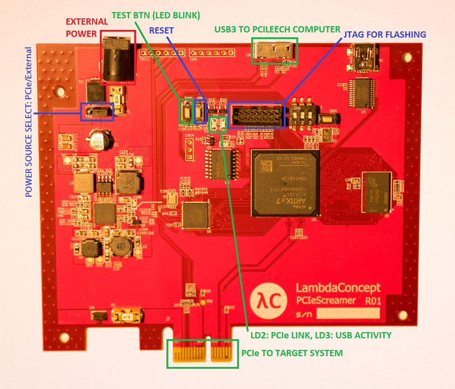
1. Select power source
For PCIe power supply, put the jumper on the left position.
For External supply via jack CN4, put the jumper on the right position. Input voltage: 5V to 15V max.
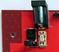
When the power supply is stable, the LED LD4 will be red.
2. Select Boot mode (R01 only)
SW2 selects the FPGA bootmode. Set it to Master SPI:
1: ON
2: OFF
3: OFF
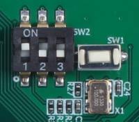
Once booted, FPGA prog done LED LD3 will be green.
Gateware & Software
PCILeech recommended.
Refer to the official PCILeech README and gateware for PCIeScreamer R01/R02